

Communication Cables Incorporating Twisted Pair Components
U.S. Patent 9,922,754
I know a thing or two about running internet/communication cables. As a hands on electrical engineer patent attorney, I have wired a number of internet connections. This invention titled “Communication Cables Incorporating Twisted Pair Components” appears on first glance of the drawings to be six internet cables packaged in one cord. However, after reviewing the additional figures, it may relate to any time of communication cables. If I’m correct, this makes a lot sense. It would be much cleaner to run cables if six cables (or whatever number of cables) were packed together. Less mess and less clutter. It also appears that heat transfer is the scope of the patent. The patent makes twenty claims directed towards the channel running down the center of the cable.
On March 20, 2018, Week 12, Number 1448-3, the United States Patent and Trademark Office published issued U.S. Patent Number 9,922,754 in the electricity Section H. The patent describes
A wide variety of different types of communication cables incorporate twisted pair conductors. In a wide variety of applications, when a twisted pair cable is installed and utilized, relatively higher amounts of heat may be generated in certain portions of the cable. For example, with a cable installed in a data center, portions of the cable situated in relatively close proximity to electronic equipment and/or equipment cabinets (e.g., portions of the cable near terminating ends) may become hotter than other portions of the cable. Additionally, electronic equipment connected to or near the termination ends of the cable may generate heat. The heat may negatively impact both the electrical performance of the cable and the performance of electronic equipment associated with the cable. Further, when a plurality of twisted pair cables are used in relatively close proximity to one another, relatively higher amounts of heat may be generated, thereby exacerbating electrical performance issues. Accordingly, there is an opportunity for improved cables that provide for heat transfer that assists in cooling the cable and/or any associated electronic equipment.
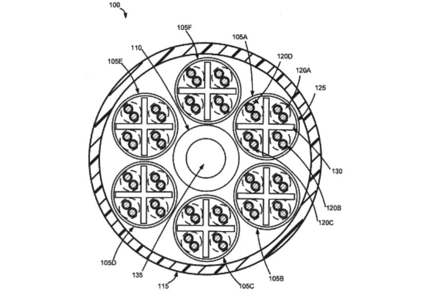
Figure 1 describes:
As shown in FIG. 1, the cable 100 may include a plurality of twisted pair components 105A-F arranged or positioned around a central member 110. The central member 110 may facilitate convective heat transfer within the cable, thereby assisting in cooling and/or normalizing the temperature of the twisted pair components. An outer jacket 115 may then be formed around the twisted pair components 105A-F and the central member 110. The cable 100 of FIG. 1 includes six twisted pair components 105A-F formed around the central member 110. In this six around one design, the central member 110 may have a size (e.g., diameter, cross-sectional area, etc.) that is approximately equal to that of each of the twisted pair components 105A-F. In other embodiments, other arrangements and/or dimensions may be utilized for the central member 110 and twisted pair components 105A-F. Additionally, components other than twisted pair components may be arranged or positioned around the central member 110. Each of the components illustrated in FIG. 1 is described in greater detail below.
Any number of twisted pair components, such as the illustrated six twisted pair components 105A-F may be incorporated into the cable 100. Additionally, in certain embodiments, the twisted pair components 105A-F may be formed or positioned around the central member 110 at any given cross-sectional point along a longitudinal length of the cable. For example, the twisted pair components 105A-F may be stranded or helically twisted about the central member 110 with a wide variety of suitable pitches or twist lays. For example, in certain embodiments, the twisted pair components 105A-F may be stranded around the central member 110 with a twist lay between approximately 150 mm and approximately 1800 mm.
Although the cable 100 of FIG. 1 illustrates a single layer or ring of twisted pair components 105A-F formed around the central member 100, in other embodiments, a plurality of layers or rings of twisted pair components may be incorporated into the cable 100. Additionally or alternatively, in certain embodiments, components other than twisted pair components may be incorporated into a cable. For example, optical fiber cable components, coaxial cable components, power cable components, spacers, and/or a wide variety of other suitable components may be incorporated into one or more layers that are stranded around the central member 110.
The patent claims, inter alia
A cable comprising:
a central member extending lengthwise along a longitudinal length of the cable, the central member comprising a channel extending lengthwise and defining a longitudinal cavity through the central member, the channel comprising a cross-sectional area of at least approximately 0.8 mm2;
a plurality of unjacketed twisted pair components formed around the central member, each twisted pair component comprising a plurality of twisted pairs of individually insulated electrical conductors; and
a jacket formed around the central member and the plurality of twisted pair components.
After a review of the patent claims review broad claims in nature. These claims can likely provide great benefit to the inventor and company of the product if the cooling benefits are found to be worth the cost to product the product.
If you have a great idea, contact a patent attorney to learn how to protect your idea.